Process multiple copies of data using an Edge Processor
Use the branch command when you want to process or route the same initial set of data in multiple distinct ways.
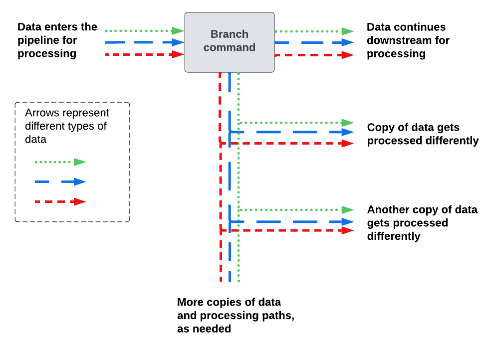
The branch command does the following:
- Creates 2 or more paths in the pipeline.
- Copies all of the incoming data in the pipeline.
- Sends the copied data to all of the newly created paths.
The following diagram shows how the branch command sends data to different paths in the pipeline.
Add the branch command to a pipeline
- In the SPL2 editor, replace the
| into $destination;command with the following:| branch [<processing_commands> | into <destination1>], [<processing_commands> | into <destination2>], [<processing_commands> | into <destination3>];This syntax creates 3 pipeline paths, but you can include more or fewer paths as necessary. The placeholders are defined as follows:
- <processing_commands> is one or more SPL2 commands for processing the data in the given pipeline path. Each command must be delimited by a pipe ( | ). If you don't want to make any changes to the data, you can leave this part empty.
- <destination> is an SPL2 variable indicating the destination that you want to send the copied data to. SPL2 variables must begin with a dollar sign ( $ ) and can be composed of uppercase or lowercase letters, numbers, and the underscore ( _ ) character.
For example:
$pipeline = | from $source | branch [ | eval index="buttercup" | into $first_destination], [ | eval index="splunk" | into $second_destination], [ | eval index="cisco" | into $third_destination]; - For each <destination> variable in the pipeline, do the following:
- In the Actions section of the pipeline builder, select Send data to <destination>, where <destination> is the SPL2 variable that you specified.
- Select the destination that you want to send the data to, and then select Apply.
- (Optional) Select the Preview Pipeline icon (
 ) to generate a preview that shows what your data looks like when it passes through the pipeline. In the preview results panel, use the drop-down list to select the pipeline path that you want to preview.
Example: Process and route the same logs in 3 different ways
In this example, your Edge Processor is receiving Cisco syslog data such as the following:
<13>Jan 09 01:54:40 10.10.232.91 : %ASA-3-505016: Module Sample_prod_id3 in slot 1 application changed from: sample_app2 version 1.1.0 state Sample_state1 to: Sample_server_name2 1.1.0 state Sample_state1.
<19>Jan 09 01:54:40 10.10.136.129 : %ASA-1-505015: Module Sample_prod_id2 in slot 1 , application up sample_app2 , version 1.1.0
<91>Jan 09 01:54:40 10.10.144.67 : %FTD-5-505012: Module Sample_prod_id1 in slot 1 , application stopped sample_app1 , version 2.2.1
<101>Jan 09 01:54:40 10.10.219.51 : %FTD-1-505011: Module 10.10.94.98 , data channel communication is UP.
Assume that you want to do the following:
- Extract IP addresses to a dedicated field, and then obfuscate the values so that they aren't directly readable by humans.
- Process and route 3 copies of this data in different ways, as follows:
Pipeline path Actions 1 - Mask the IP address in the
_rawfield. - Send the data to Amazon S3 bucket.
2 - Extract the log message number to a field named
msg_num. - Drop the
_rawfield. - Send the data to an index named cisco_msg_num in a Splunk Enterprise instance.
3 - Extract the severity level of the log to a field named
severity. - Drop the
_rawfield. - Send the data to an index named cisco_severity in a Splunk Cloud Platform deployment.
- Mask the IP address in the
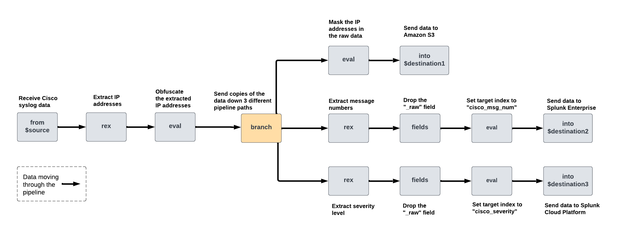
You can achieve this by creating a pipeline that extracts and obfuscates the IP address, and then uses the branch command to create 3 pipeline paths. Then, in each path, add the necessary SPL2 commands to complete the data processing actions described in each table row. The following diagram shows the commands that this pipeline contains and how the data gets processed as it moves through the pipeline:
To create this pipeline, do the following:
- On the Pipelines page, select New pipeline. Follow the on-screen instructions to define a partition and optionally enter sample data. Skip the step for selecting a data destination.
After you complete the on-screen instructions, the pipeline builder displays the SPL2 statement for your pipeline. - Extract the IP addresses from the logs to a field named
ip_address.- In the Actions section, select the plus icon (
 ) and then select Extract fields from _raw.
 - Select Insert from library, and then select IPv4WithOptionalPort.
- In the Regular expression field, change the name of the capture group from IPv4WithOptionalPort to ip_address. The updated regular expression looks like this:
(?P<ip_address>(((?:2(?:5[0-5]|[0-4][0-9])|[0-1][0-9][0-9]|[0-9][0-9]?)(?:\.(?:2(?:5[0-5]|[0-4][0-9])|[0-1][0-9][0-9]|[0-9][0-9]?)){3}))(?::(?:[1-9][0-9]*))?) - Select Apply.
The pipeline builder adds the following
rexcommand to your pipeline:| rex field=_raw /(?P<ip_address>(((?:2(?:5[0-5]|[0-4][0-9])|[0-1][0-9][0-9]|[0-9][0-9]?)(?:\.(?:2(?:5[0-5]|[0-4][0-9])|[0-1][0-9][0-9]|[0-9][0-9]?)){3}))(?::(?:[1-9][0-9]*))?)/ - In the Actions section, select the plus icon (
- Obfuscate the IP addresses.
- In the Actions section, select the plus icon (
 ) and then select Compute hash of.
 - In the Compute hash of a field dialog box, configure the following options and then select Apply.
Option name Enter or select the following Source field ip_address Hashing algorithm SHA-256 Target field ip_address The pipeline builder adds the following
evalcommand to your pipeline:| eval ip_address = sha256(ip_address)
The preview results panel shows data that looks like the following. Note that the original IP addresses are still visible in the
_rawfield._raw ip_address <13>Jan 09 01:54:40 10.10.232.91 : %ASA-3-505016: Module Sample_prod_id3 in slot 1 application changed from: sample_app2 version 1.1.0 state Sample_state1 to: Sample_server_name2 1.1.0 state Sample_state1. 646e8e63709c12d8217a18531e72c4d1d84df4f1766d982d312eb012ead1026b <19>Jan 09 01:54:40 10.10.136.129 : %ASA-1-505015: Module Sample_prod_id2 in slot 1 , application up sample_app2 , version 1.1.0 7c1fce7e82260857a7863778c573abc500e1859fce122c4556936fd6c0480eed <91>Jan 09 01:54:40 10.10.144.67 : %FTD-5-505012: Module Sample_prod_id1 in slot 1 , application stopped sample_app1 , version 2.2.1 e6736cc2f5f06144c16ad670e2e729a966aba3f1be84b9f21d17e06cfa42f99a <101>Jan 09 01:54:40 10.10.219.51 : %FTD-1-505011: Module 10.10.94.98 , data channel communication is UP. be4b991dd91306c3a451154e81ff74e48508989af4c67fec2129b1c85bdb15c4 - In the Actions section, select the plus icon (
- Use a
branchcommand to process and route this set of data in 3 different ways. In the SPL2 editor, replace the| into $destinationcommand with abranchcommand using this format:| branch [<processing_commands> | into $destination1], [<processing_commands> | into $destination2], [<processing_commands> | into $destination3];Because each pipeline path is sending data to a different destination, each path ends with its own
intocommand, and the| into $destinationcommand that the pipeline builder included by default is no longer needed.To complete the 3 sets of data processing actions that were described at the beginning of this example, you would need to configure the following commands in each pipeline path:
Pipeline path Actions SPL2 commands 1 Mask the IP address in the _rawfield.| eval _raw=replace(_raw, /<(?P<priority>.*)>(?P<month>[A-z]{3})\s(?P<date>[0-9]{2}?)\s(?P<time>[0-9]+:[0-9]+:[0-9]+)\s(?P<hostname>(([0-9]|[1-9][0-9]|1[0-9]{2}|2[0-4][0-9]|25[0-5]).){3}([0-9]|[1-9][0-9]|1[0-9]{2}|2[0-4][0-9]|25[0-5]))\s:\s(?P<body>.*)/, "<\\1> \\2 \\3 \\4 x.x.x.x \\9")2 - Extract the log message number to a field named
msg_num. - Drop the
_rawfield. - Send the data to an index named cisco_msg_num.
| rex field=_raw /(?P<msg_num>(%ASA|%FTD)-\d+-\d+)/
| fields - _raw
| eval index="cisco_msg_num"
3 - Extract the severity level of the log to a field named
severity. - Drop the
_rawfield. - Send the data to an index named cisco_severity.
| rex field=_raw /(%ASA|%FTD)-(?P<severity>\d)/
| fields - _raw
| eval index="cisco_severity"
The completed
branchcommand looks like this:| branch [ | eval _raw=replace(_raw, /<(?P<priority>.*)>(?P<month>[A-z]{3})\s(?P<date>[0-9]{2}?)\s(?P<time>[0-9]+:[0-9]+:[0-9]+)\s(?P<hostname>(([0-9]|[1-9][0-9]|1[0-9]{2}|2[0-4][0-9]|25[0-5]).){3}([0-9]|[1-9][0-9]|1[0-9]{2}|2[0-4][0-9]|25[0-5]))\s:\s(?P<body>.*)/, "<\\1> \\2 \\3 \\4 x.x.x.x \\9") | into $destination1 ], [ | rex field=_raw /(?P<msg_num>(%ASA|%FTD)-\d+-\d+)/ | fields - _raw | eval index="cisco_msg_num" | into $destination2 ], [ | rex field=_raw /(%ASA|%FTD)-(?P<severity>\d)/ | fields - _raw | eval index="cisco_severity" | into $destination3 ]; - Extract the log message number to a field named
- In the Actions section of the pipeline builder, do the following:
- Select Send data to $destination1. Select an Amazon S3 destination for the first set of processed data, and then select Apply.
- Select Send data to $destination2. Select a Splunk Enterprise destination for the second set of processed data, and then select Apply.
- Select Send data to $destination3. Select a Splunk Cloud Platform destination for the third set of processed data, and then select Apply.
You now have a pipeline that sends 3 differently processed sets of data to 3 different destinations. You can use the preview results panel to confirm the data that is sent to each destination.
Set the drop-down list to $destination1 to confirm that the following logs will be sent to Amazon S3:
| _raw | ip_address |
|---|---|
| <13>Jan 09 01:54:40 x.x.x.x : %ASA-3-505016: Module Sample_prod_id3 in slot 1 application changed from: sample_app2 version 1.1.0 state Sample_state1 to: Sample_server_name2 1.1.0 state Sample_state1. | 646e8e63709c12d8217a18531e72c4d1d84df4f1766d982d312eb012ead1026b |
| <19>Jan 09 01:54:40 x.x.x.x : %ASA-1-505015: Module Sample_prod_id2 in slot 1 , application up sample_app2 , version 1.1.0 | 7c1fce7e82260857a7863778c573abc500e1859fce122c4556936fd6c0480eed |
| <91>Jan 09 01:54:40 x.x.x.x : %FTD-5-505012: Module Sample_prod_id1 in slot 1 , application stopped sample_app1 , version 2.2.1 | e6736cc2f5f06144c16ad670e2e729a966aba3f1be84b9f21d17e06cfa42f99a |
| <101>Jan 09 01:54:40 x.x.x.x : %FTD-1-505011: Module 10.10.94.98 , data channel communication is UP. | be4b991dd91306c3a451154e81ff74e48508989af4c67fec2129b1c85bdb15c4 |
Set the drop-down list to $destination2 to confirm that the following logs will be sent to Splunk Enterprise:
| index | ip_address | msg_num |
|---|---|---|
| cisco_msg_num | 646e8e63709c12d8217a18531e72c4d1d84df4f1766d982d312eb012ead1026b | %ASA-3-505016 |
| cisco_msg_num | 7c1fce7e82260857a7863778c573abc500e1859fce122c4556936fd6c0480eed | %ASA-1-505015 |
| cisco_msg_num | e6736cc2f5f06144c16ad670e2e729a966aba3f1be84b9f21d17e06cfa42f99a | %FTD-5-505012 |
| cisco_msg_num | be4b991dd91306c3a451154e81ff74e48508989af4c67fec2129b1c85bdb15c4 | %FTD-1-505011 |
Set the drop-down list to $destination3 to confirm that the following logs will be sent to Splunk Cloud Platform:
| index | ip_address | severity |
|---|---|---|
| cisco_severity | 646e8e63709c12d8217a18531e72c4d1d84df4f1766d982d312eb012ead1026b | 3 |
| cisco_severity | 7c1fce7e82260857a7863778c573abc500e1859fce122c4556936fd6c0480eed | 1 |
| cisco_severity | e6736cc2f5f06144c16ad670e2e729a966aba3f1be84b9f21d17e06cfa42f99a | 5 |
| cisco_severity | be4b991dd91306c3a451154e81ff74e48508989af4c67fec2129b1c85bdb15c4 | 1 |
The complete SPL2 statement of the pipeline looks like this:
$pipeline = | from $source
| rex field=_raw /(?P<ip_address>(((?:2(?:5[0-5]|[0-4][0-9])|[0-1][0-9][0-9]|[0-9][0-9]?)(?:\.(?:2(?:5[0-5]|[0-4][0-9])|[0-1][0-9][0-9]|[0-9][0-9]?)){3}))(?::(?:[1-9][0-9]*))?)/
| eval ip_address = sha256(ip_address)
| branch
    [
        | eval _raw=replace(_raw, /<(?P<priority>.*)>(?P<month>[A-z]{3})\s(?P<date>[0-9]{2}?)\s(?P<time>[0-9]+:[0-9]+:[0-9]+)\s(?P<hostname>(([0-9]|[1-9][0-9]|1[0-9]{2}|2[0-4][0-9]|25[0-5]).){3}([0-9]|[1-9][0-9]|1[0-9]{2}|2[0-4][0-9]|25[0-5]))\s:\s(?P<body>.*)/, "<\\1> \\2 \\3 \\4 x.x.x.x \\9")
        | into $destination1
    ],
    [
        | rex field=_raw /(?P<msg_num>(%ASA|%FTD)-\d+-\d+)/
        | fields - _raw
        | eval index="cisco_msg_num"
        | into $destination2
    ],
    [
        | rex field=_raw /(%ASA|%FTD)-(?P<severity>\d)/
        | fields - _raw
        | eval index="cisco_severity"
        | into $destination3
    ];
See also
For information about other ways to route data, see Routing data in the same Edge Processor pipeline to different actions and destinations.
| Process a copy of data using an Edge Processor | Route internal logs from forwarders using an Edge Processor |
This documentation applies to the following versions of Splunk Cloud Platform™: 9.0.2209, 9.0.2303, 9.0.2305, 9.1.2308, 9.1.2312, 9.2.2403, 9.2.2406, 9.3.2408 (latest FedRAMP release), 9.3.2411


 Download manual
Feedback submitted, thanks!